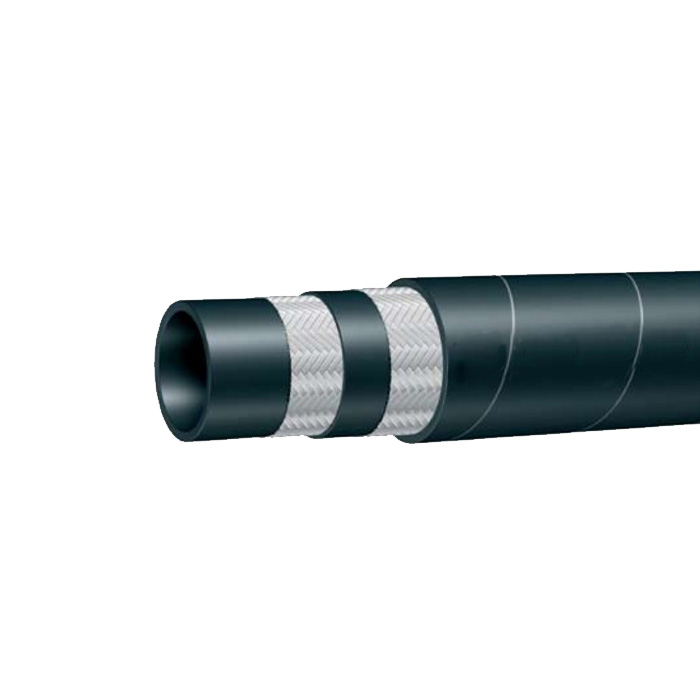
Wire braid and spiral layers are the main reinforcement structures that allow a high pressure hose to handle extreme internal pressure, repeated bending, and millions of pressure cycles. Wire braid designs usually provide better flexibility, while spiral layers offer higher pressure resistance and stronger impulse performance. For example, SAE-rated hydraulic hoses can operate from around 7 MPa to more than 40 MPa depending on reinforcement design, and burst pressure ratings are often several times higher than working pressure.
A hydraulic hose contains three main sections: the inner tube, reinforcement layer, and outer cover. The inner tube transports hydraulic fluid, but it cannot resist high internal pressure alone. When fluid pressure increases, the rubber tube tends to expand outward. The reinforcement layer limits this expansion by carrying tensile forces around the hose structure.
In industrial systems, pressure levels can change thousands of times during daily operation. A construction machine may complete more than 100,000 hydraulic cycles during regular service, making reinforcement design important for long-term reliability.
“The steel reinforcement layer controls hose expansion and allows hydraulic pressure to be carried safely through the hose structure.”
The reinforcement layer is mainly made from high-strength steel wire arranged in different patterns. The two common designs are braided wire reinforcement and spiral wire reinforcement. Although both use steel wires, their mechanical behavior is different because the wire arrangement changes how forces are distributed.
Wire braid reinforcement uses steel wires crossed over each other at an angle, usually around 45° to 55°. This structure allows the hose to handle pressure from different directions while maintaining flexibility. Two-wire braid hoses are widely used in mobile hydraulic equipment because they can bend repeatedly without losing strength.
A typical two-wire braid hydraulic hose may support working pressures between 15 MPa and 30 MPa depending on size and material selection. In applications such as loaders, agricultural equipment, and industrial machinery, flexibility is often needed because hose assemblies move with cylinders and rotating components.
The braid angle affects performance because it controls the balance between pressure resistance and flexibility. A lower braid angle generally improves resistance to axial force, while a higher angle allows better control of diameter expansion.
| Reinforcement structure | Typical working pressure | Main characteristics |
|---|---|---|
| Single wire braid | 5–15 MPa | Flexible and suitable for general systems |
| Two wire braid | 15–30 MPa | Balanced pressure strength and flexibility |
| Four spiral wire | 35–45 MPa | Designed for heavy-duty pressure systems |
| Six spiral wire | Above 45 MPa in some designs | Used for extreme hydraulic applications |
The flexibility advantage of braided reinforcement comes with certain limitations. Because braided wires cross each other, small movements can occur between wire contact points when pressure changes repeatedly. Over long service periods, repeated movement may increase wear between wires and reduce fatigue resistance.
This limitation leads to the use of spiral reinforcement in systems that require higher pressure capability. Spiral layers arrange steel wires in several separate layers wound around the hose tube. Each layer usually crosses at opposite directions, creating a balanced structure that improves pressure handling.
Spiral hoses are commonly selected for mining equipment, injection molding machines, and heavy construction systems where hydraulic pressure may exceed 35 MPa. Four-wire and six-wire spiral designs are often tested under hundreds of thousands of impulse cycles before approval.
“Spiral reinforcement reduces wire movement during pressure changes, allowing the hose to maintain strength under repeated high-pressure operation.”
The working principle of spiral layers is based on tensile force distribution. When hydraulic pressure pushes outward on the inner tube, spiral wires resist this expansion by carrying the force along their length. Multiple reinforcement layers share the load instead of allowing one layer to absorb most of the stress.
For example, a four-spiral hose with alternating wire directions can distribute pressure forces across several layers. Compared with a single reinforcement layer, multiple spiral layers can increase pressure capability by more than 50% depending on hose size and construction method.
The difference between braid and spiral structures can be seen in several performance areas:
| Performance factor | Wire braid hose | Spiral hose |
|---|---|---|
| Flexibility | Higher | Lower |
| Maximum pressure capability | Medium to high | Very high |
| Impulse resistance | Good | Excellent |
| Bending frequency | Higher | Moderate |
| Typical use | Mobile equipment | Heavy industrial systems |
Material quality also affects reinforcement performance. Hydraulic hose manufacturers use steel wires with tensile strengths commonly above 1,500 MPa. The wire surface is treated to improve bonding with rubber layers because weak adhesion can allow separation during pressure cycling.
A properly manufactured hose depends on accurate wire placement, rubber bonding, and curing temperature control. Even a small change in reinforcement angle or wire spacing can influence pressure resistance and service performance.
Modern high pressure hydraulic hoses are designed according to international standards such as SAE J517 and EN 853/856. These standards define requirements for pressure rating, impulse testing, dimensions, and material performance. A hose assembly rated at 35 MPa may be tested at much higher pressure levels to confirm safety margins.
Temperature conditions also affect reinforcement performance. Hydraulic equipment can operate from below -40°C in cold environments to above 100°C near engines or industrial machines. Steel reinforcement keeps its mechanical strength across these temperature ranges, while rubber materials must maintain flexibility and adhesion.
Pressure impulse testing is one of the main evaluation methods for high-pressure hoses. During testing, hoses are repeatedly pressurized and depressurized under controlled conditions. Some hydraulic hose standards require thousands of impulse cycles, while specialized applications may require hundreds of thousands of cycles.
“A hose that handles static pressure but fails under repeated pressure changes does not meet the requirements of many industrial systems.”
The choice between wire braid and spiral reinforcement depends on the equipment design, pressure level, movement frequency, and expected service environment. A mobile hydraulic arm with continuous movement may benefit from braid reinforcement because bending flexibility is important. A mining hydraulic system operating at 40 MPa may require spiral reinforcement because pressure endurance is more important.
The outer cover also works together with reinforcement layers. It protects the internal structure from abrasion, oil exposure, weather conditions, and mechanical damage. In construction environments, hose covers may face contact with metal edges, dust, and temperature changes every day.
Proper reinforcement design helps reduce unexpected hose replacement and improves machine availability. In industries where hydraulic failure can stop production for hours, selecting the correct wire structure can reduce maintenance frequency and improve equipment operation.
Wire braid and spiral layers are essential because they provide the mechanical strength required for hydraulic hoses to operate under high pressure. Braid structures offer flexibility and balanced performance, while spiral structures provide greater pressure capacity and fatigue resistance. The correct reinforcement design allows hydraulic systems to operate safely through repeated pressure changes, heavy loads, and demanding working conditions.